Rust Embedded Development: Displaying Images on ST7789 Screen
Guide on displaying images on ST7789 screens using Rust embedded development, including image format conversion techniques from common formats to supported formats like BMP, TGA, and QOI.
embedded-graphics is the standard for display graphics in Rust embedded development, so we can use it to display images.
However, embedded-graphics doesn’t support common image formats like png, jpg, etc.
From the documentation, we learn that embedded-graphics only supports bmp, tga, and qoi formats.
In fact, it’s not that simple. The ST7789 screen doesn’t support RGB888 (also called 24-bit RGB) color format. Through documentation research, we know that the ST7789 screen only supports RGB565 (16-bit) color format.
So the solution is straightforward: we just need to convert the image from 24-bit to 16-bit color space and convert it to bmp, tga, or qoi format to display it on the screen.
Converting Images
You can use a Python script to convert any image format to the formats mentioned above.
For example, here’s a script I implemented to convert jpg to tga:
def convert_jpg_to_tga_rgb565(input_path: str, output_path: Optional[str] = None, size: Tuple[int, int] = (64, 64)) -> str:
    """
    Resize JPG image and convert to RGB565 format TGA

    Args:
        input_path: Input JPG image path
        output_path: Output TGA image path (optional, defaults to input filename.tga)
        size: Target size, defaults to (64, 64)

    Returns:
        Output file path
    """
    input_path_obj = Path(input_path)

    # Determine output path
    if output_path is None:
        output_path_obj = input_path_obj.with_suffix('.tga')
    else:
        output_path_obj = Path(output_path)

    output_path_str = str(output_path_obj)

    # Open image
    with Image.open(input_path_obj) as img:
        # Convert to RGB mode
        if img.mode != 'RGB':
            img = img.convert('RGB')

        # Resize to specified dimensions
        img_resized = img.resize(size, Image.Resampling.LANCZOS)

        # RGB565 layout: bit15-11=red(5 bits), bit10-5=green(6 bits), bit4-0=blue(5 bits)
        pixel_data = bytearray()
        for r, g, b in img_resized.getdata():
            r5 = (r >> 3) & 0x1F   # Red: 8-bit to 5-bit
            g6 = (g >> 2) & 0x3F   # Green: 8-bit to 6-bit
            b5 = (b >> 3) & 0x1F   # Blue: 8-bit to 5-bit
            # Combine into 16-bit RGB565: high->low = RRRRR GGGGGG BBBBB
            pixel565 = (r5 << 11) | (g6 << 5) | b5
            pixel_data.append(pixel565 & 0xFF)
            pixel_data.append((pixel565 >> 8) & 0xFF)

    header = bytearray(18)
    header[0] = 0    # ID length
    header[1] = 0    # Color map type
    header[2] = 2    # Image type: uncompressed true-color
    header[3] = 0    # Color map spec: first entry low
    header[4] = 0    # Color map spec: first entry high
    header[5] = 0    # Color map spec: length low
    header[6] = 0    # Color map spec: length high
    header[7] = 0    # Color map spec: depth
    header[8] = 0    # X origin low
    header[9] = 0    # X origin high
    header[10] = 0   # Y origin low
    header[11] = 0   # Y origin high
    header[12] = size[0] & 0xFF      # Width low
    header[13] = (size[0] >> 8) & 0xFF  # Width high
    header[14] = size[1] & 0xFF      # Height low
    header[15] = (size[1] >> 8) & 0xFF  # Height high
    header[16] = 16  # Bits per pixel
    header[17] = 0x20  # Image descriptor: bit 5=1 (origin at bottom-left)

    # Write TGA file
    with open(output_path_str, 'wb') as f:
        f.write(header)
        f.write(pixel_data)

    return output_path_str
Note that you need to be careful whether you’re converting to RGB565( RRRRR GGGGGG BBBBB) or BGR565( BBBBB GGGGGG RRRRR). Both are supported, and this is very important - it will be relevant later.
The order is mainly controlled by the following code:
# BGR565
pixel565 = (b5 << 11) | (g6 << 5) | r5

# RGB565
pixel565 = (r5 << 11) | (g6 << 5) | b5
Jpg to bmp (rgb565) conversion is roughly as follows:
def convert_jpg_to_bmp_rgb565(input_path: str, output_path: Optional[str] = None, size: Tuple[int, int] = (128,128)) -> str:
    """
    Convert JPG image to 16-bit RGB565 format BMP (BITFIELDS format)

    Args:
        input_path: Input JPG image path
        output_path: Output BMP image path (optional, defaults to input filename.bmp)
        size: Target size, defaults to 64x64

    Returns:
        Output file path
    """
    input_path_obj = Path(input_path)

    if not input_path_obj.exists():
        raise FileNotFoundError(f"Input file not found: {input_path}")

    # Determine output path
    if output_path is None:
        output_path_obj = input_path_obj.with_suffix('.bmp')
    else:
        output_path_obj = Path(output_path)

    output_path_str = str(output_path_obj)

    # Open image
    with Image.open(input_path_obj) as img:
        # Convert to RGB mode
        if img.mode != 'RGB':
            img = img.convert('RGB')

        # Resize to specified dimensions
        img_resized = img.resize(size, Image.Resampling.LANCZOS)

        # Get all pixel data
        all_pixels = list(img_resized.getdata())
        width, height = size

        # BMP is bottom-up format, need to store rows from bottom
        # i.e., first row of pixel data corresponds to the bottom of the image
        pixel_data = bytearray()
        for y in range(height - 1, -1, -1):  # Start from bottom
            for x in range(width):
                r, g, b = all_pixels[y * width + x]
                # RGB565: R:5 bits, G:6 bits, B:5 bits
                r5 = (r >> 3) & 0x1F
                g6 = (g >> 2) & 0x3F
                b5 = (b >> 3) & 0x1F
                # Combine into 16-bit: RRRRR GGGGGG BBBBB
                pixel565 = (r5 << 11) | (g6 << 5) | b5
                # Little-endian storage
                pixel_data.append(pixel565 & 0xFF)
                pixel_data.append((pixel565 >> 8) & 0xFF)

        # Create BITFIELDS format BMP header (70 bytes)
        header = create_bitfields_bmp_header(size[0], size[1], len(pixel_data))

        # Write BMP file
        with open(output_path_str, 'wb') as f:
            f.write(header)
            f.write(pixel_data)

    return output_path_str
Driving Image Display
TGA and BMP images use these two libraries respectively:
tinytga = "0.5.0"
tinybmp = "0.7.0"
Here I’ll use the following image as an example to display on the ST7789 screen:

The core code is minimal, roughly as follows:
    // Need to clear the screen, otherwise previous content will be displayed
    display.clear(Rgb565::BLACK).unwrap();

    let data = include_bytes!("../../jing.tga");
    let img: Tga<Rgb565> = Tga::from_slice(data).unwrap();

    // If using a bmp image, use the following code
    // let data = include_bytes!("../../jing.bmp");
    // let img: Bmp<Rgb565> = Bmp::from_slice(data).unwrap();

    let image = Image::new(&img, Point::zero());
    image.draw(&mut display.color_converted()).unwrap();

    loop {
        delay.delay_millis(500);
    }
2 Major Pitfalls
Both of the following pitfalls can cause color display errors similar to this:
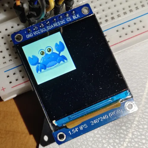
First pitfall: Rgb565 or Bgr565?
When converting, you must pay attention to the order. If you converted to Rgb, then use Tga<Rgb565> during initialization. If it’s Bgr, then use Tga<Bgr565> during initialization.
Also, when initializing the screen, you need to set:
let mut display = Builder::new(ST7789, di)
        .reset_pin(rst)
        .color_order(mipidsi::options::ColorOrder::Rgb) //<======== Set to Rgb or Bgr here
        .init(&mut delay)
        .unwrap();
Second pitfall: Screen color inversion
You might, like me, fall into the second pitfall after getting out of the first one. I don’t know if it’s my initialization issue or a problem with the mipidsi driver, but by default if you do nothing and just set this:
display.clear(Rgb565::BLACK).unwrap();It displays as white on the screen. For example, my previous temperature and humidity screen interface:
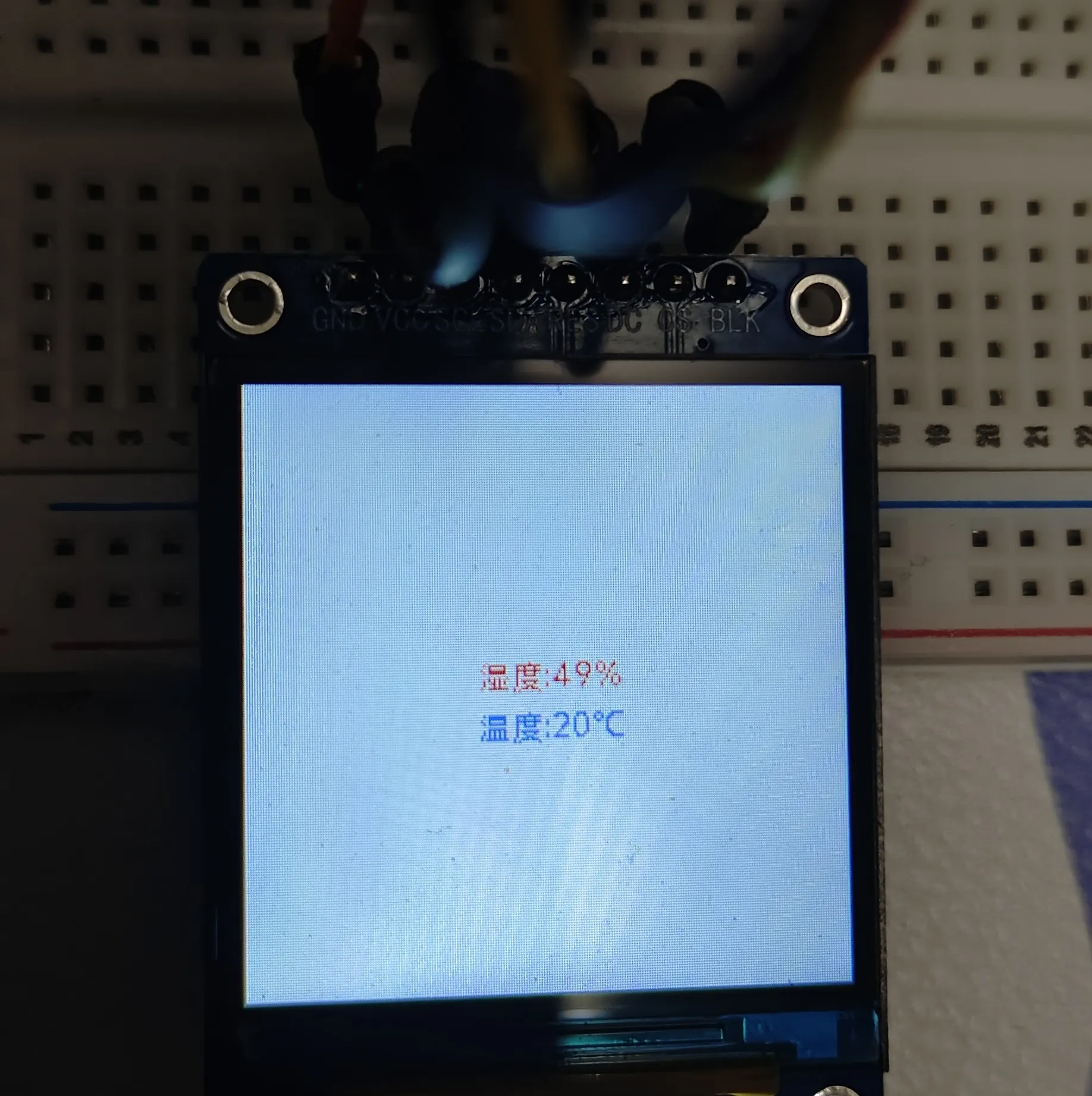
You can see that I set Rgb565::BLACK, but the screen displays white. This problem didn’t occur with C language.
The solution is to add the following parameter when initializing the screen to invert the screen colors:
    let mut display = Builder::new(ST7789, di)
        .reset_pin(rst)
        .color_order(mipidsi::options::ColorOrder::Rgb)
        // Invert screen colors
        .invert_colors(mipidsi::options::ColorInversion::Inverted)
        .init(&mut delay)
        .unwrap();
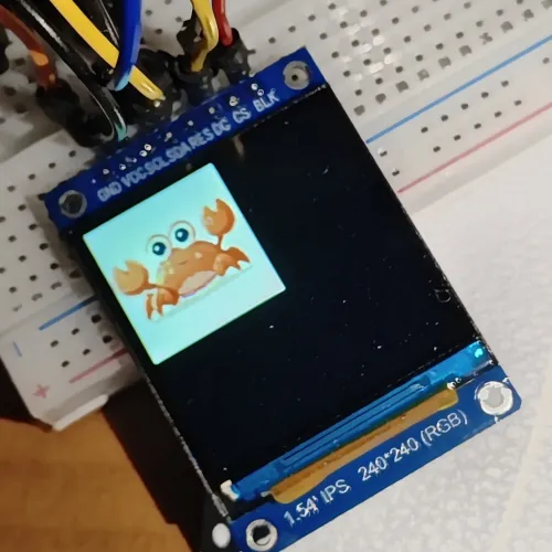
The final result is as follows:
Complete Code
#![no_std]
#![no_main]
#![deny(
    clippy::mem_forget,
    reason = "mem::forget is generally not safe to do with esp_hal types, especially those \
    holding buffers for the duration of a data transfer."
)]
#![deny(clippy::large_stack_frames)]

use embedded_graphics::prelude::RgbColor;
use embedded_graphics::{
    Drawable,
    image::Image,
    pixelcolor::{Rgb565, Bgr565},
    prelude::{DrawTarget, DrawTargetExt, OriginDimensions, Point, Size},
};
use embedded_hal_bus::spi::ExclusiveDevice;
use esp_alloc as _;
use esp_hal::main;
use esp_hal::{clock::CpuClock, delay::Delay, gpio, spi::master::Config, time::Rate};
use mipidsi::{Builder, interface::SpiInterface, models::ST7789, options::Orientation};
use tinybmp::Bmp;
use tinytga::Tga;
#[panic_handler]
fn panic(_: &core::panic::PanicInfo) -> ! {
    loop {}
}

extern crate alloc;

esp_bootloader_esp_idf::esp_app_desc!();

#[allow(
    clippy::large_stack_frames,
    reason = "it's not unusual to allocate larger buffers etc. in main"
)]
#[main]
fn main() -> ! {
    // static mut APP_CORE_STACK: Stack<8192> = Stack::new();
    let mut delay = Delay::new();
    let config = esp_hal::Config::default().with_cpu_clock(CpuClock::max());
    let peripherals = esp_hal::init(config);

    // LCD display initialization
    let dc = gpio::Output::new(peripherals.GPIO15, gpio::Level::Low, Default::default());
    let mut rst = gpio::Output::new(peripherals.GPIO7, gpio::Level::Low, Default::default());
    rst.set_high();
    let cs = gpio::Output::new(peripherals.GPIO16, gpio::Level::High, Default::default());
    let spi = esp_hal::spi::master::Spi::new(
        peripherals.SPI2,
        Config::default().with_frequency(Rate::from_mhz(30)),
    )
    .unwrap()
    .with_sck(peripherals.GPIO5)
    .with_mosi(peripherals.GPIO6);

    let spi_device = ExclusiveDevice::new_no_delay(spi, cs).unwrap();
    let mut buffer = [0_u8; 512];

    let di = SpiInterface::new(spi_device, dc, &mut buffer);
    let mut display = Builder::new(ST7789, di)
        .reset_pin(rst)
        .color_order(mipidsi::options::ColorOrder::Rgb)
        .invert_colors(mipidsi::options::ColorInversion::Inverted)
        .init(&mut delay)
        .unwrap();
    // Need to clear the screen, otherwise previous content will be displayed
    display.clear(Rgb565::BLACK).unwrap();

    let data = include_bytes!("../../jing.tga");
    let img: Tga<Rgb565> = Tga::from_slice(data).unwrap();

    // let data = include_bytes!("../../jing.bmp");
    // let img: Bmp<Bgr565> = Bmp::from_slice(data).unwrap();


    let image = Image::new(&img, Point::new(64, 64));
    image.draw(&mut display.color_converted()).unwrap();

    loop {
        delay.delay_millis(500);

    }
}
Finally
Also, the size of images displayed on the ST7789 screen is limited and cannot exceed the screen resolution.